HMI-2 Arduino Fundamentals and the Serial Port
** Lecture Video **
- Background Knowledge and Prerequisites
- The Arduino Board
- Basic Inputs and Outputs
- Arduino IO
- The Serial Port
- Sending Commands to Arduino via Serial using the Serial Monitor
- Advanced Topic: Sending a stream of commands and values to the Arduino
Background Knowledge and Prerequisites
I’m assuming you are already familiar at least with the basics of microcontrollers and electronics. If not I strongly suggest you to take the time and follow this tutorials (and if you are one of my students, then it’s a must). Feel free to skip information you are already familiar with:
- Introduction to Microcontrollers Chapter 2. Microcontroller Components. Pages 11 to 72.
- C Tutorial
- Installing Arduino on a Windows Machine
- What’s an Arduino
- Bare Minimum code needed
- Blink a LED
- Using a PushButton
- Digital Read Serial
- Read Analog Voltage
The Arduino Board
So what’s and Arduino Board
Arduino is an open-source electronics platform based on easy-to-use hardware and software. Arduino boards are able to read inputs - light on a sensor, a finger on a button, or a Twitter message - and turn it into an output - activating a motor, turning on an LED, publishing something online. You can tell your board what to do by sending a set of instructions to the microcontroller on the board. To do so you use the Arduino programming language (based on Wiring), and the Arduino Software (IDE), based on Processing.
In other words, an Arduino board is a microcontroller with a bunch of other useful components attached to it, these components allow you to easily prototype and test new ideas with few lines of code an the bare minimum extra hardware.
I dare to say that Arduino may be very famous for students but it is a tabu in the industry. Experienced engineers undervalue the power of an Arduino saying it’s merely a toy. In my personal opinion an Arduino is a perfectly capable developing board for prototyping and experiments and you can even use it in real final products with some tweaks, although coding in the Arduino Programming Language is not scalable nor maintainable you can always use pure C or any other language supported by AVR.
We use an Arduino for this course because we don’t care about complicated hardware, performance or code scalaility, we are concerned only with the basics of the Serial communication and how to design an easy to use intuitive GUI.
Basic Inputs and Outputs
Microcontrollers are used because they allow a piece of hardware to interact with it’s environment “easily”.
Imagine you want to build a “robot” (just imagine it…), you want this robot to be aware of it’s environment, what I mean with this is that you want this robot to “see”, “hear”, “smell” and “feel” everything around it. You may want also to make this robot interact with the environment, you may want it to “walk” or at least “move” and avoid obstacles, or maybe you want to speak an order and make the robot obey, for example saying “make me a sandwich” will make the robot go to the fridge, fetch the ingredients and start making you a damn sandwich!!
Well that wasn’t very realistic right now, but a microcontroller can help you retrieving signals from the environment and control actuators in order to make your little wall-e behave decently.
The environment signals the microcontroller retrieve are the inputs, and logically, the signals sent to the actuators are the outputs.
So, how exactly the IO of a microcontroller works?
Digital I/O, or, to be more general, the ability to directly monitor and control hardware, is the main characteristic of microcontrollers. As a consequence, practically all microcontrollers have at least 1-2 digital I/O pins that can be directly connected to hardware (within the electrical limits of the controller). In general, you can find 8-32 pins on most controllers, and some even have a lot more than that (like Motorola’s HCS12 with over 90 I/O pins). I/O pins are generally grouped into ports of 8 pins, which can be accessed with a single byte access. Pins can either be input only, output only, or —most commonly,— bidirectional, that is, capable of both input and output.
A microcontroller like any processor works by moving around bytes in the memory, so there’s a memory assigned to each Port, wether it’s input or ouput you can use this memory to read or write values that reflects what’s physically in the real world.
Digital IO
Let’s see an example, in the next Image we have an Atmega microcontroller connected to some components.
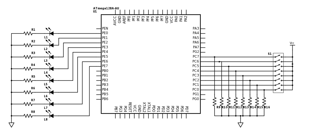
The Port E (All pins called PEx) is connected to LEDs and the Port C is connected to a DIP Switch (just an array of buttons/switches). We are going to assume here that we have declared the PORT E as output and the PORT C as input (for obvious reasons).
So what should we do if we want to turn on all those LEDs? We will need to assign to the memory PORT_E a value equal to the binary number 11111111b (xFF or 255). Why? Imagine each Pin of the port mapped to each one of the digits of that binary number, so in order to turn them all on we need to set them all to one.
PORT_E = 11111111b; //You can use binary numbers
PORT_E = 255;       //Decimal
PORT_E = xFF;       //Or Hexadecimal
That will result in all the LEDs turned on:
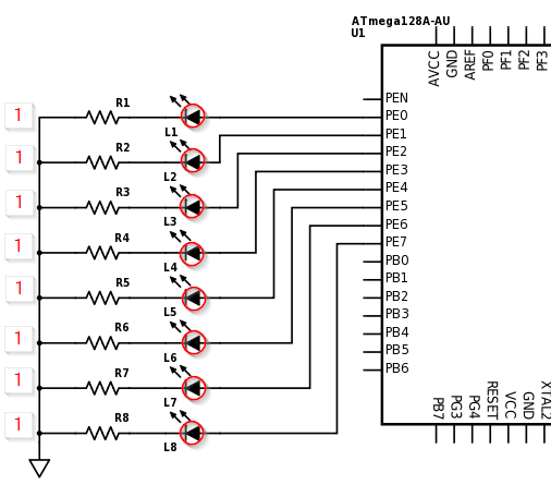
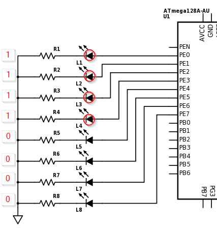
So if you want to just turn on the half of them, let’s say from pin 0 to pin 3 do:
PORT_E = 00001111b; //You can use binary numbers
PORT_E = 15;       //Decimal
PORT_E = xF;       //Or Hexadecimal
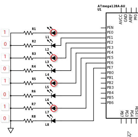
Or alternated
PORT_E = 1010101b; //You can use binary numbers
PORT_E = 85;       //Decimal
PORT_E = x55;      //Or Hexadecimal
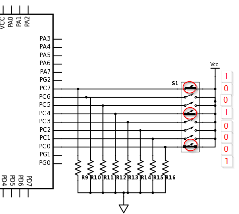
This same thing applies for the Input, so imagine you turn on the switches 0, 3 and 7. This will result in PORT_C having a value of 10001001b which is 137 in decimal or x89 in hexadecimal.
Analog IO
Now what to do if the input you want to read is not digital (It’s value is not 1 or 0, 5v or 0v…) but analog?
Then you need an Analog to Digital Converter, hopefully most microcontrollers have at least one built-in. I won’t explain the details about how a ADC works, instead I just want you to know the practical approach.
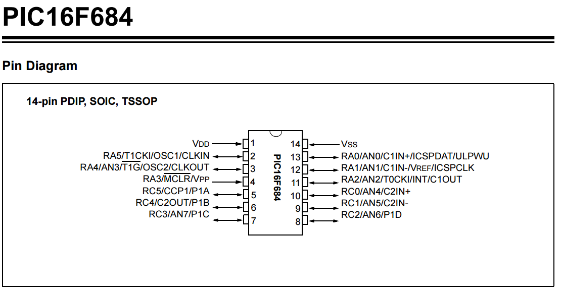
Most of Analog pins are noted as ANx, in the next datasheet you can find that the pin 13 can be used as Digital (RA0) or Analog (AN0).
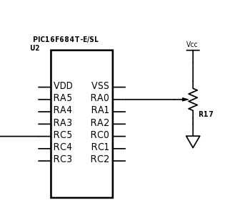
If we had a circuit like the one below with just a voltage divider (using a potenciometer) connected directly to the AN0 pin and everything is configured correctly we would be able to read analog values.
In our program an analog value will be represented as a number, this number will obey the next formula for a 10bits resolution ADC
analog_val = V_input * 1024 / VCC
So for example, if we move the potenciometer to a position in which it throws an output of 2.5v then the ADC in your program will read 512. And for 1.3v will read 266.
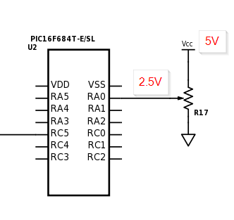
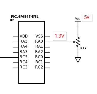
NOTE: This formula only applies if you have NOT connected the analog reference pin of the microcontroller to a different source of voltage. If you have, then just replace the VCC for your new RefVoltage. You would have something like analog_val = V_input * 1024 / RefVoltage.
PWM
Most decent microcontrollers have a PWM pin. PWM stands for Pulse Width Modulation and its widely used along microcontrollers to produce a wave very much alike to a square wave.
Pulse Width Modulation, or PWM, is a technique for getting analog results with digital means. Digital control is used to create a square wave, a signal switched between on and off. This on-off pattern can simulate voltages in between full on (5 Volts) and off (0 Volts) by changing the portion of the time the signal spends on versus the time that the signal spends off. The duration of “on time” is called the pulse width. To get varying analog values, you change, or modulate, that pulse width. If you repeat this on-off pattern fast enough with an LED for example, the result is as if the signal is a steady voltage between 0 and 5v controlling the brightness of the LED.
One key word here is Duty Cycle or DC, the DC is measured in percentage of time the wave is in High State, for the particular case of an Arduino this Duty Cycle is defined as a number of 8bits (0 - 255).
In the next image you can see different PWM wave forms with different Duty Cycles, where a DC of 0 is basically 0v all the time and a DC of 50% (defined by the number 127) will keep a the signal on High state half the time.
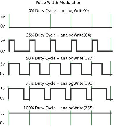
PWM signals are useful for a lot of things. Apart from their uses in simple d/a converters they can be used to implement ABS in cars, to dim LEDs or numeric displays, or for motor control (servos, stepper motors, speed control of dc motors).
Arduino IO
I’ll use an Arduino UNO which uses an ATmega328P as an example for Inputs and Outputs.
In the next image there’s a typical Arduino UNO board.
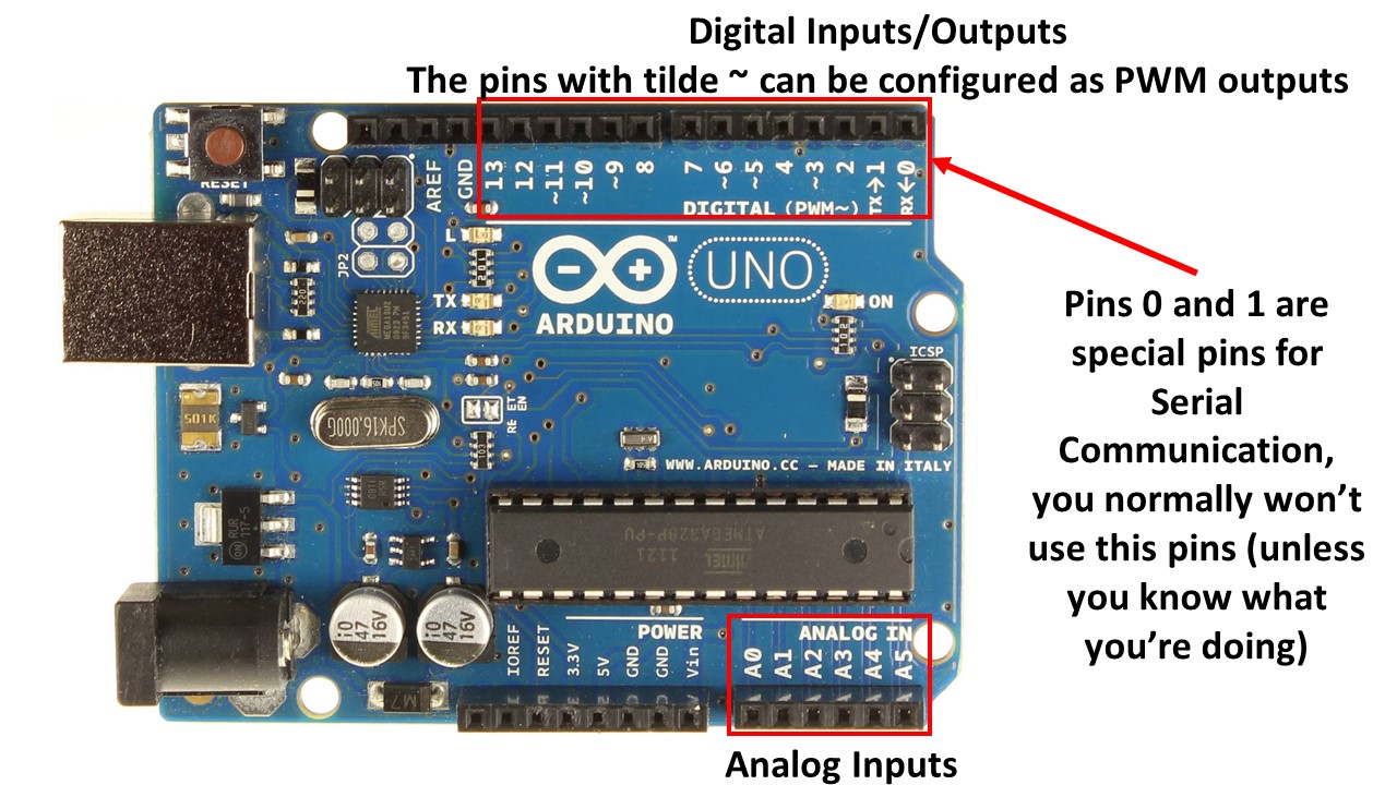
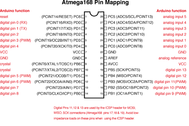
Here is how the pins of the microcontroller (Atmega168) are mapped to the board terminals, remember that the number printed in front of the Terminal/Header could not be the same as the Pin Number in the Atmega328, the creators of Arduino have abstracted the real pin numbers in order for you to be easy to program an Arduino Board and to make Portable all the code between different models.
This image was extracted from here. If you want to see the full schematic visit: link.
So, how do we use an Arduino to control inputs and outputs? Just one answer: Very easy! Lets think you have the next diagram:
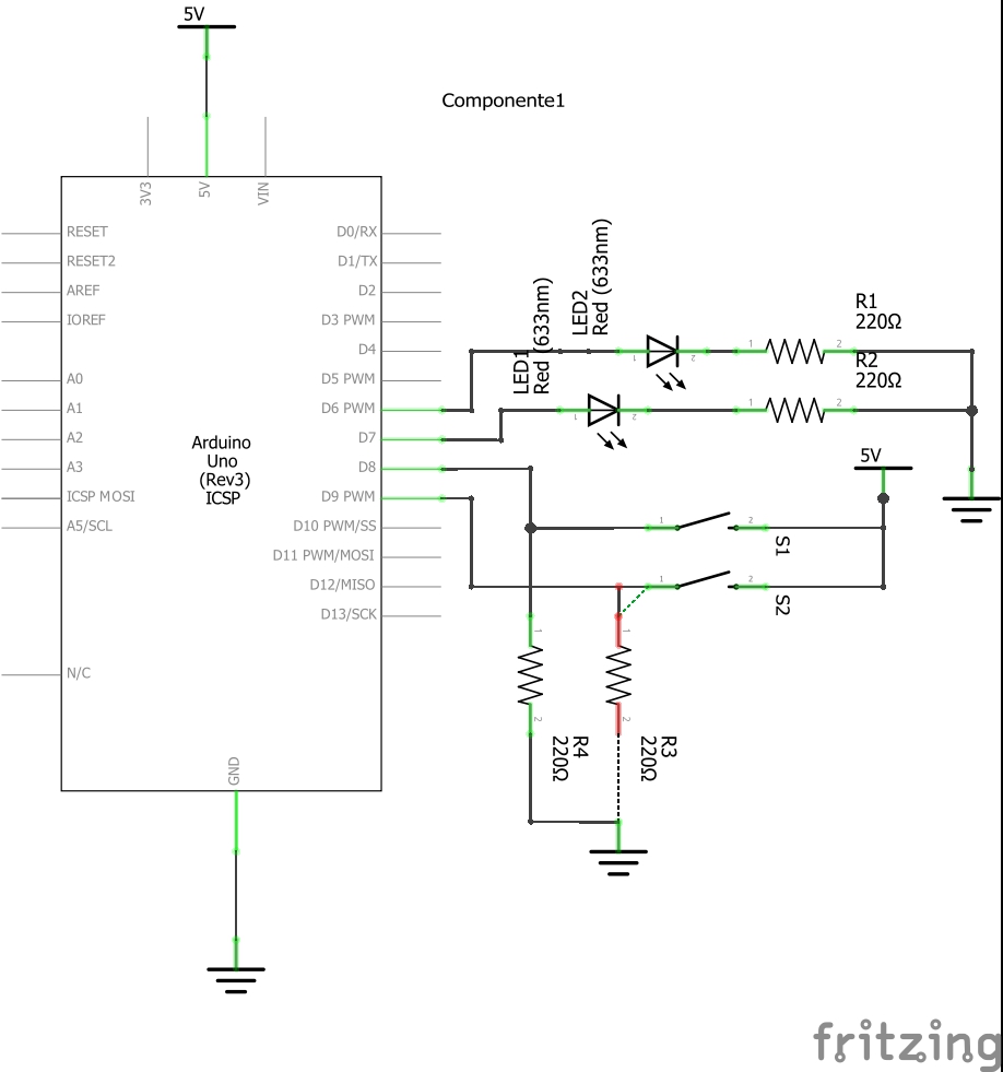
And if you feel inspired and you want to build it, here is how it would look like in a Protoboard:
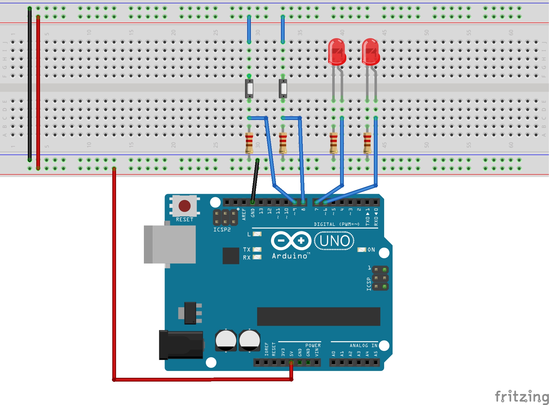
The goal is to press the Push Buttons and make the LEDs Turn On in a fashion way. So when you press Push 1 LED1 will turn on and LED2 will turn off. When you press Push 2 the LEDs will swap that state, LED1 will turn Off and LED2 will turn on.
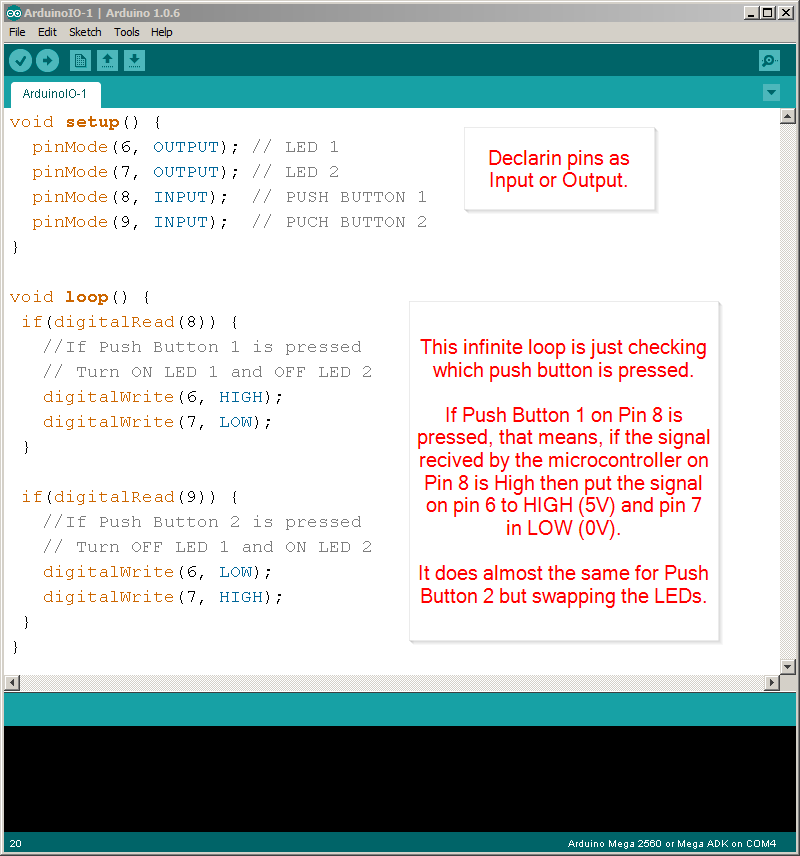
This is the code to do that:
/*
  Hazael Fernando Mojica Garcia
  09/July/2017
  Example: HMI-2-ArduinoIO-Simple
*/
void setup() {
  pinMode(6, OUTPUT); // LED 1
  pinMode(7, OUTPUT); // LED 2
  pinMode(8, INPUT);  // PUSH BUTTON 1
  pinMode(9, INPUT);  // PUSH BUTTON 2
}

void loop() {
 if(digitalRead(8)) {
   //If Push Button 1 is pressed
   // Turn ON LED 1 and OFF LED 2
   digitalWrite(6, HIGH);
   digitalWrite(7, LOW);
 }

 if(digitalRead(9)) {
   //If Push Button 2 is pressed
   // Turn OFF LED 1 and ON LED 2
   digitalWrite(6, LOW);
   digitalWrite(7, HIGH);
 }
}
Take note that we are using very few code and there are some special functions you will be using very often:
pinMode(pinNumber, MODE);To declare a pin as INPUT or OUTPUT. Ref Here.digitalWrite(pinNumber, STATE);To make a pin have HIGH or LOW output signal. Ref Here.digitalRead(pinNumber)Reads the value of a pin. Which could be HIGH (1) or LOW (0). Ref Here.
All these functions as you may have notice control the state of a single pin not the whole port, this is a peculiarity of Arduino, the Arduino compiler handles for you the boiler plate code to make reference a single pin instead of a complete port in order for you to easily use it. This is good or bad depending of what you need to accomplish.
Feel free to implement the next examples if you think you need some more practice in order to understand the basics of Arduino IO:
- Arduino Button
- Arduino State Change Detection
- Arduino Blink Without Delay
- Arduino Analog Input
- Arduino Debounce
Example: Using multiple input/outputs
Now let’s see a practical example using many inputs and outputs.
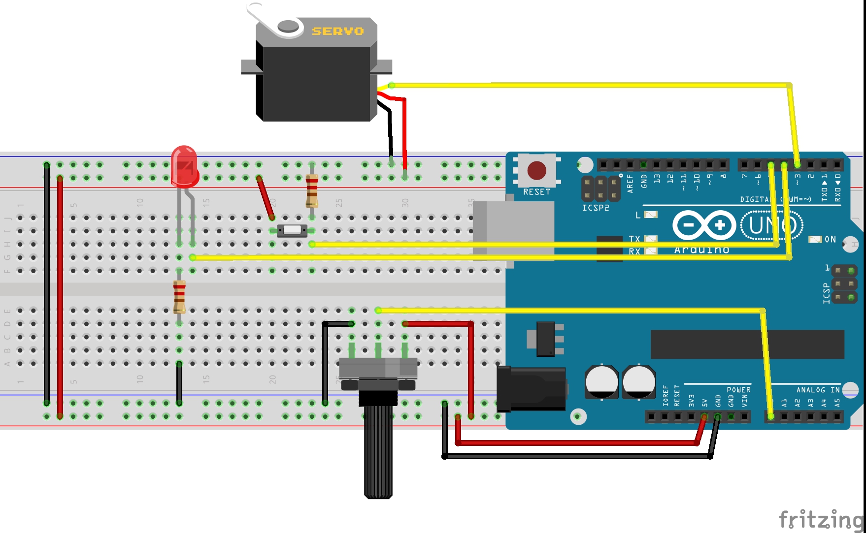
The goals of this example are:
- Control the movement of a Servo motor using a potentiometer. When the pot is set to give an output of 0V the degrees advanced in the servo will be 0° and when the pot output is 5V the servo will advance the full length of 180°.
- Control the blinking interval of a LED using a push button. Each time the user presses the push button the LED will blink faster, starting from a 2sec period and up to a 50ms period.
The protoboard view is in this picture
And the schematic is:
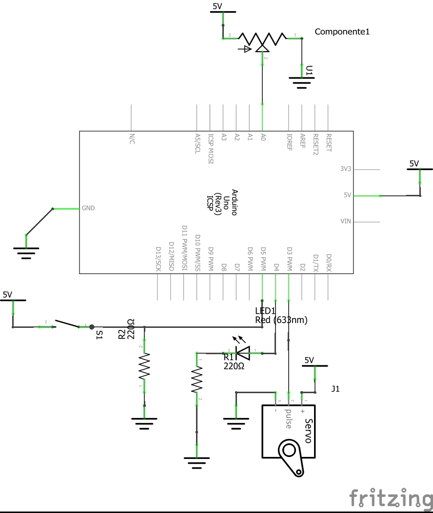
The Arduino Code is:
/*
  Hazael Fernando Mojica Garcia
  09/July/2017
  Example: HMI-2-ArduinoIO-Multi
*/

int pinServo = 3;
int pinLED = 4;
int pinPush = 5;
int pinPotA = 0;
int LEDState = 0;
int pushState = 0;

unsigned int intervalLED = 2000;
unsigned int intervalPush = 500;
unsigned int intervalServo = 100;

unsigned long pastMillisLED = 0;
unsigned long pastMillisServo = 0;
unsigned long pastMillisPush = 0;

unsigned long currentMillis = 0;

void setup() {
  pinMode(pinServo, OUTPUT);//PWM pin as output
  pinMode(pinLED, OUTPUT);
  pinMode(pinPush, INPUT);
}

void loop() {
  currentMillis = millis();

  if((currentMillis - pastMillisLED) >= intervalLED) {
    //This block will be executed each intervalLED ms
    blinkLED();
    pastMillisLED = currentMillis;
  }

  if((currentMillis - pastMillisServo) >= intervalServo) {
    //This block will be executed each intervalServo ms
    moveServo();
    intervalServo = currentMillis;
  }

  if((currentMillis - pastMillisPush) >= intervalPush) {
    //This block will be executed each intervalPush ms
    changeBlinkInterval();
    intervalPush = currentMillis;
  }
}

void blinkLED() {
  LEDState = 1 - LEDState;//Swap LED state
  digitalWrite(pinLED, LEDState);//Blink LED
}

void moveServo() {
  int potVal = analogRead(pinPotA);//potVal from 0 to 1023
  analogWrite(pinServo, potVal/4);//Output PWM from 0 to 255
}

void changeBlinkInterval() {
  int newPushState = digitalRead(pinPush);
  if(pushState && !newPushState) {
    //Change interval when the user
    //is no more pressing the button
    intervalLED -= 50;//Decrease 50ms
    if(intervalLED < 50) {
      intervalLED = 2000; //Reset the Interval
    }
  }
  pushState = newPushState;
}
Mount everything in your Arduino and try it out.
Code Explained:
This code structure is based in time invervals, we want to be able to execute some code periodically, we don’t want it to run everytime the main loop comes back again, that would be disastrous setting up the PWM for a Servo, we don’t want to use delay functions either because it’s a waste of processing resources since once the micro enters in a delay routine it cannot do anything else until it’s done.
What do we do then? In embedded software you normally would use a RTOS (Real Time Operative System) or Interruptions, the creators of Arduino actually use both inside Arduino’s kernel code, but they decided not to let us touch them, instead they provide us with a function called millis(), this function returns an unsigned long number which represents the milliseconds elapsed since the arduino was turned on. So, using a clever if statement we can build some sort of task manager:
if((currentMillisecond - pastMilliseconds) >= interval) {
    //This code will be executed each interval milliseconds
    pastMilliseconds = currentMillisecond;
}
In the code above all variables represent milliseconds values, remember to use only unsigned long variables for this kind of work.
The Serial Port
Now we are going to talk about of the main the Serial Port, which is a valuable asset we need in order for our Arduino to have communication with other devices such a computer or other microcontroller.
So, What’s a Serial Port?
To answer this question I want you to know that there are multiple types of communication interfaces:
… microcontrollers generally contain several communication interfaces and sometimes even multiple instances of a particular interface, like two UART modules. The basic purpose of any such interface is to allow the microcontroller to communicate with other units, be they other microcontrollers, peripherals, or a host PC. The implementation of such interfaces can take many forms, but basically, interfaces can be categorized according to a hand-full of properties: They can be either serial or parallel, synchronous or asynchronous, use a bus or point-to-point communication, be full-duplex or half duplex, and can either be based on a master-slave principle or consist of equal partners.
So a Serial Port is an interface that allows communication between to devices sending data sequentially, bit per bit, one at a time. As you can see this method only requires one data line, or one wire you might say, to send data, maybe another to receive data, one extra wire to share a voltage reference (GND) and maybe if the communication is synchronous a Clock wire.
Serial interfaces stream their data, one single bit at a time. These interfaces can operate on as little as one wire, usually never more than four.
Example of a serial interface, transmitting one bit every clock pulse. Just 2 wires required! (The Image is property of Sparkfun):

The UART
The Universal Asynchronous Receiver Transmitter is one implementation of the Serial Interface, one which only uses two wires, TXD and RXD, for transmitting and receiving data accordingly.
In order to make two devices communicate over a Serial UART Interface you need to set both using the same configuration:
- Data bits
- Synchronization bits
- Parity bits
- Baud rate
Baud Rate This attribute specifies how fast the data is sent. It’s expressed in bits-per-second (bps).
The Baud Rate in the both devices must be the same, the typical values are: 1200, 4800, 9600, 115200. The higher the baud rate the faster the data is sent, but keep in mind the clock speed configuration in your micro, you could get errors in the data if the micro just can’t keep up with high speeds of transmition.
Bits Data over UART is sent in packets of bits, as you can see in the next image (property of Sparkfun).

The synchronization bits are used to mark the start and end of each package. The line is in High state when idle, so the Start bit is a 0 and the Stop bit is 1 making up the idle state again.
The Data bits hold the info you want to send, they may vary from 5 to 9 bits but Arduino uses by default an 8 bit data packets.
The parity bits are used for low-level error checking in the 5-9 data bits. You can configure them for odd or even check.
For example, assuming parity is set to even and was being added to a data byte like 0b01011101, which has an odd number of 1’s (5), the parity bit would be set to 1. Conversely, if the parity mode was set to odd, the parity bit would be 0.
They are not widely used and I won’t need for this course so I’ll skip a deeper explanation.
** Hardware **
Wiring an UART is easy, the bus consist just of two wires, one for transmitting, one for receiving and one reference (Image property of Sparkfun (property of Sparkfun).
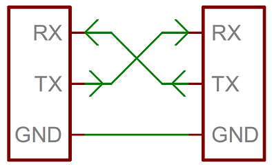
Note that the RX wire of one device goes to the TX of the other and vice-versa.
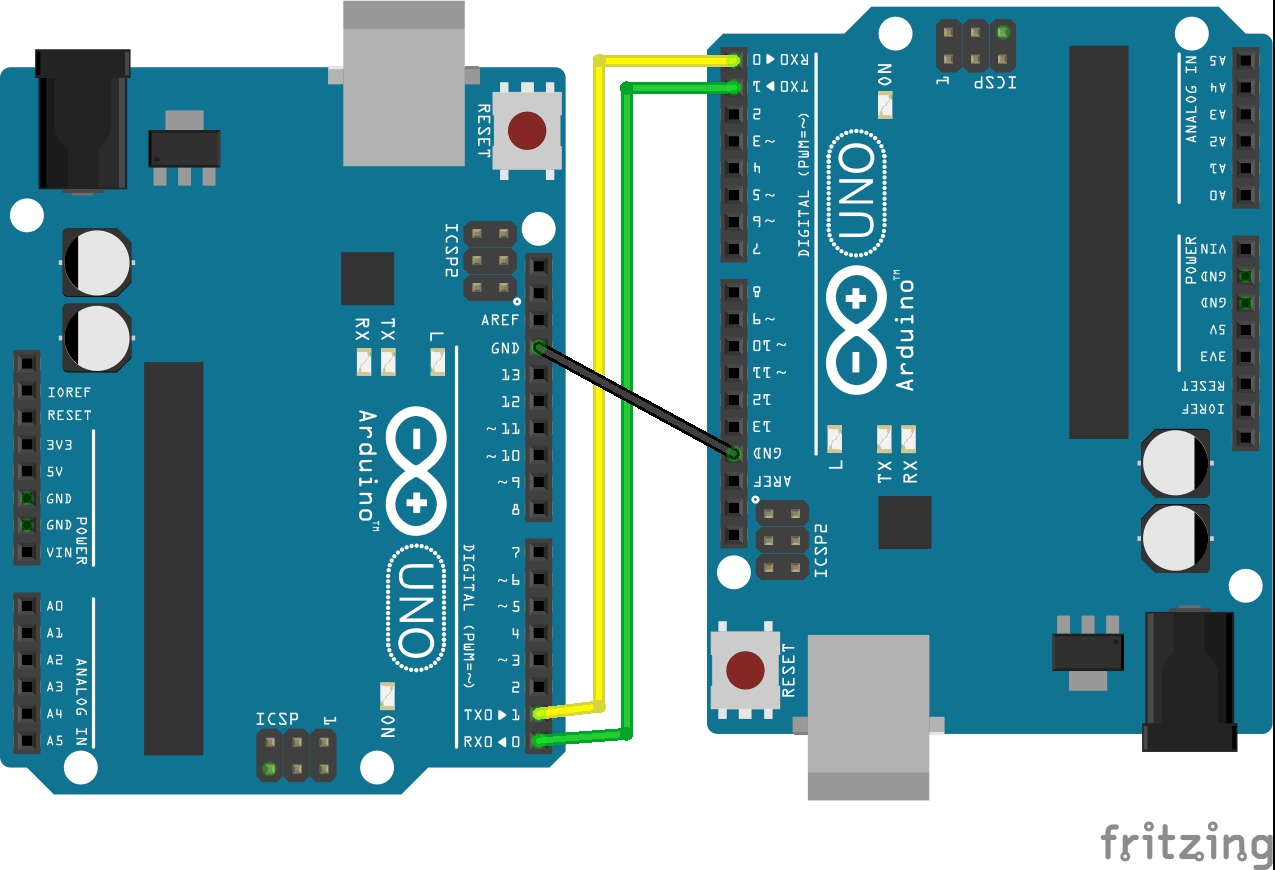
If you wanted to implement Serial communication between two arduino devices you would need at least to wire up everything as in the following image:
** Talking to a computer **
If you haven’t notice earlier, every Arduino has Serial communication with a computer out of the box (which is used for programming the arduino) and this is one of the main reasons we are using it in this course.
It has everything prepared to allow easy Serial UART communication with a PC, if you check the Arduino UNO schematic below you can notice how the TXD and RXD pins of the ATMEGA8 micro are wired to another smaller one (ATMEGA8U2) which only purpose is to handle a USB stack to create a virtual Serial Port in a PC.

The same could have been accomplished using an FTDI chip, but the creators of Arduino likes to complicate things up.
So in summary if you want to allow any microcontroller to easily communicate over Serial UART with a computer you just need a UART able micro and an FTDU chip.
Serial Communication in the Industry
Many Serial protocols are widely used in the industry nowadays, and some of them we use at home too.
For the automotive industry the CAN protocol is the leader, the MCU of the car communicates with all the devices a car has over a CAN network, the air bags, brakes, cameras, weigth sensors, door sensors etc…
For communicating devices inside the same PCB board it’s common to see protocols like IC2 or SPI.
And you should remember connecting your computer or Blu-Ray player to a TV over an HMI cable.
Sending Commands to Arduino via Serial using the Serial Monitor
In order to make a custom program that communicates over the Serial Port of a PC we need first to know how to handle serial communication.
The Serial Monitor is a simple software utility you can use to send and receive charaters over the Serial port, it comes integrated in the Arduino IDE. You can open it clicking in the little magnifier glass icon in the right upper corner of the Arduino IDE:
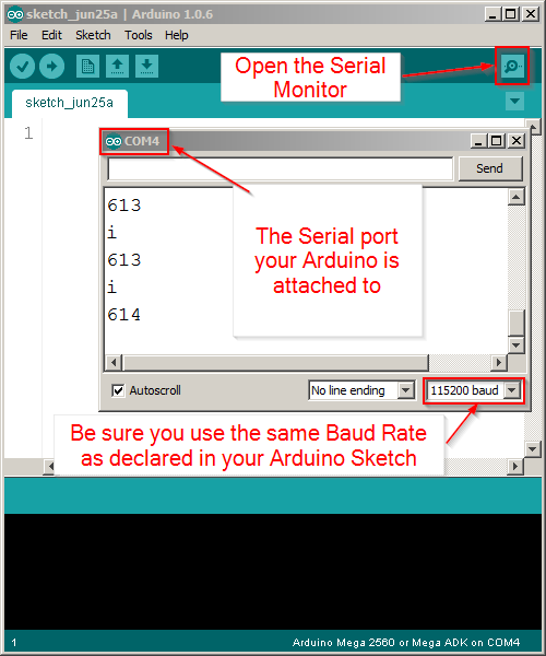
You 3 need things to make it work:
- Your Arduino is connected via USB to the computer
- Drivers are installed (your Arduino has a Serial port COMx assigned to it)
- In the Menu Tools -> Serial Port you have choosed the serial port your arduino is attached to
You can use any other tool to do this job, there are plenty available, just google them, I personally recommend Termite, but there’s also the oldschool HyperTerminal, Real Term, PuTTY and many others.
Example: Turn On/Off via Serial
In this easy example we will just turn on/off an LED sending a command via Serial.
/*
* Hazael Fernando Mojica García
* 25/June/2017
* HMI-2-Serial-ONOFF
*/

int pinLED = 2;

void setup() {
  Serial.begin(115200);
  pinMode(pinLED, OUTPUT);
}

void loop() {
  if(Serial.available()) {
    switch(Serial.read()) {
      case 'a':
        digitalWrite(pinLED, HIGH);
      break;

      case 'b':
        digitalWrite(pinLED, LOW);
      break;
    }
  }
}
Here the protoboard view:
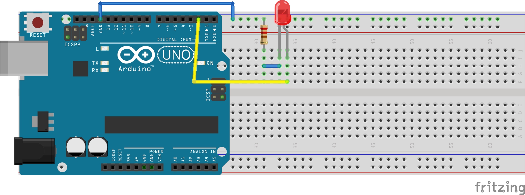
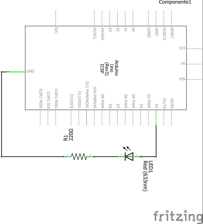
Here the schematic:
Now, a brief explanation:
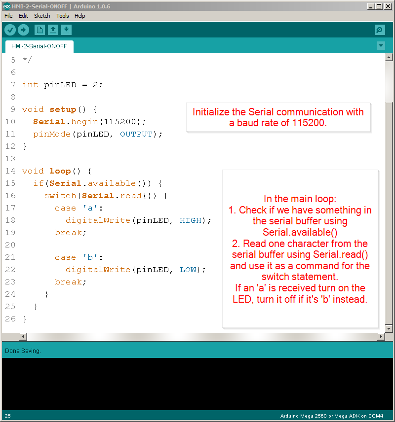
In the main setup() function we need to initialize the Serial communication with a baud rate of 115200.
In the main loop of the program we need to do something to handle “commands” received by serial. Using the Serial.available() function, which returns true or false depending of wether we have a character in the serial buffer or not, we will be sure we need to handle a new income command and with Serial.read() we get that one character from that buffer and immediately we process it inside a switch statement.
So, once you have everything connected to the protoboard, plug the arduino to the computer and open the Serial monitor, send an ‘a’ and watch how the LED turns on, now send ‘b’ and it should turn off.

NOTE: Once you click the Serial Monitor, wait for it 1 sec to ‘warm up’ before sending anything, each time you open it the Arduino Board gets rebooted, so it takes its time to answer. Also when I say you should send ‘a’ I mean you just send a, ignore the apostrophe (‘).
Example: Controlling multiple input/output’s via Serial
Now let’s do some more awesome stuff, using the same hardware setup as in the example “Using multiple input/outputs” we are going to add Serial communication magic to make the project controllable over the Serial Monitor.
We are going to use the same structure as the previous example: sending individual commands over the serial port with the arduino always ready to catch and execute them on the fly.
Here the code:
/*
* Hazael Fernando Mojica García
* 25/June/2017
* HMI-2-Serial-Multi
*/

int pinServo = 3;
int pinLED = 4;
int pinPush = 5;
int pinPotA = 0;

int pwmVal = 0;

void setup() {
  Serial.begin(115200);
  pinMode(pinServo, OUTPUT);//PWM pin as output
  pinMode(pinLED, OUTPUT);
  pinMode(pinPush, INPUT);
}

void loop() {
  if(Serial.available()) {
    switch(Serial.read()) {
      case 'a'://Turn On LED
        setLEDval(1);
      break;

      case 'b'://Turn Off LED
        setLEDval(0);
      break;

      case 'c'://Increase servo PWM
        increaseServo();
      break;

      case 'd'://Decrease servo PWM
        decreaseServo();
      break;

      case 'e'://Read Digital Val
        readDigitalVal();
      break;

      case 'f'://Read Analog Value
        readAnalogVal();
      break;
    }
  }
}

void setLEDval(int stat) {
  if(stat) {
    digitalWrite(pinLED, HIGH);
    Serial.println("LED ON");
  } else {
    digitalWrite(pinLED, LOW);
    Serial.println("LED OFF");
  }
}

void increaseServo() {
  pwmVal += 10;
  if(pwmVal > 255) {
    pwmVal = 255;
  }
  setPWMVal();
}

void decreaseServo() {
  pwmVal -= 10;
  if(pwmVal < 0) {
    pwmVal = 0;
  }
  setPWMVal();
}

void setPWMVal() {
  analogWrite(pinServo, pwmVal);
  Serial.print("PWM val: ");
  Serial.println(pwmVal);
}

void readDigitalVal() {
  if(digitalRead(pinPush)) {
    Serial.println("Push val: HIGH");
  } else {
    Serial.println("Push val: LOW");
  }
}

void readAnalogVal() {
  //analogRead(pinPotA) will return a value between
  //0 and 1023, dividing it by 4 we made it fit in 8 bits
  Serial.print("Analog val: ");
  Serial.println(analogRead(pinPotA)/4);
}
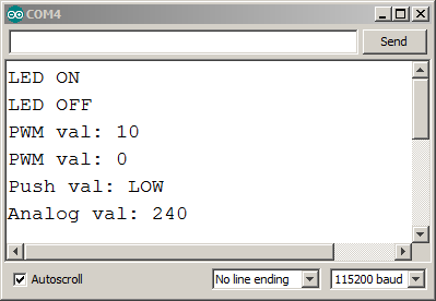
You can test this program by opening the Serial Monitor and sending the characters ‘a’, ‘b’, ‘c’, ‘d’, ‘e’, ‘f’ one by one and waiting for the proper response, you would get something like:
Advanced Topic: Sending a stream of commands and values to the Arduino
So far we’ve been sending individual commands to the arduino, but these commands are finite, you can make up to 256 different commands and sometimes that would not be enough for the requeriments of your project.
For example, let’s say you want to set up the PWM that controlls a Servo Motor by sending the value directly over Serial. Using the previous structure we had before you have two options:
- Increase or decrease the pwm value until you have what you want, if a computer software is the one sending the command via Serial, then it will need to send an “increase” or “decrease” command, wait for the reply and then keep doing that until the desired value is reached.
- Use the 8bit character to set the PWM value. This is faster, but you won’t be able to send anything else over the Serial Port.
There are plenty of solutions for this problem, some of them with better performance compared with the solution I give here, anyway here we go!
We need to send a “command” and a “value” to the Arduino over Serial, so instead of sending just an 8bit number that represents a simple command, we will send a stream of characters.
So, instead of sending just ‘a’, ‘b’, ‘c’ now we will send: “1-225” where 1 is the command number and 225 the value attached to it.
In order to separate a unique command-value pair from others we will use a ‘&’ character. Finally the stream will look like: “1-225&2-30&1-1023&3-1&3-0&1-10” As you can see it looks pretty ordered, command 1 with a value of 225 followed by command 2 with a value of 30, again command 1 changing with a value of 1023 and so forth.
Now let’s see the Arduino code that can handle a stream of characters for controlling multiple IO in the next example.
NOTE: I used a String object, if your not sure how to use a String in the C code for Arduino please visit: Arduino String
Example: Controlling multiple input/output’s via Serial using a stream of commands
Using the same hardware setup as in the example “Using multiple input/outputs” load the next program to the Arduino:
/*
* Hazael Fernando Mojica García
* 25/June/2017
* HMI-2-Serial-Stream
*/

int pinServo = 3;
int pinLED = 4;
int pinPush = 5;
int pinPotA = 0;

//A buffer to store the incoming serial data
String commandBuffer = "";
String valueBuffer = "";
int appendStatus = 0;      //0 No append
                           //1 Append to command
                           //2 Append to value

void setup() {
  Serial.begin(115200);
  pinMode(pinServo, OUTPUT);//PWM pin as output
  pinMode(pinLED, OUTPUT);
  pinMode(pinPush, INPUT);
}

void loop() {
  readSerialBuffer();
}

void readSerialBuffer() {
  if(Serial.available()) {
    char character = Serial.read();
    if(character == '&') {
      //We got a & separator
      //Execute the last command in buffer if valid
      executeCommand();
      appendStatus = 1;
    } else if (character == '-') {
      appendStatus = 2;
    } else {
      append2Buffer(character);
    }
  }
}

void append2Buffer(char val2append) {
  if(appendStatus == 1) {
    commandBuffer += val2append;
  } else if (appendStatus == 2) {
    valueBuffer += val2append;
  }
}

void executeCommand() {
  int command = commandBuffer.toInt();
  int value = valueBuffer.toInt();
  executeCommandImpl(command, value);
  commandBuffer = "";
  valueBuffer = "";
}

void executeCommandImpl(int command, int value) {
  //By convention the command 0 is an invalid command
  switch(command) {
    case 1://set LED
      setLEDval(value);
    break;

    case 2://set servo PWM
      setPWMVal(value);
    break;

    case 3://Read Digital Val
      readDigitalVal();
    break;

    case 4://Read Analog Value
      readAnalogVal();
    break;
  }
}

void setLEDval(int stat) {
  if(stat) {
    digitalWrite(pinLED, HIGH);
    Serial.println("LED ON");
  } else {
    digitalWrite(pinLED, LOW);
    Serial.println("LED OFF");
  }
}

void setPWMVal(int val) {
  analogWrite(pinServo, val);
  Serial.print("PWM val: ");
  Serial.println(val);
}

void readDigitalVal() {
  if(digitalRead(pinPush)) {
    Serial.println("Push val: HIGH");
  } else {
    Serial.println("Push val: LOW");
  }
}

void readAnalogVal() {
  //analogRead(pinPotA) will return a value between
  //0 and 1023, dividing it by 4 we made it fit in 8 bits
  Serial.print("Analog val: ");
  Serial.println(analogRead(pinPotA)/4);
}
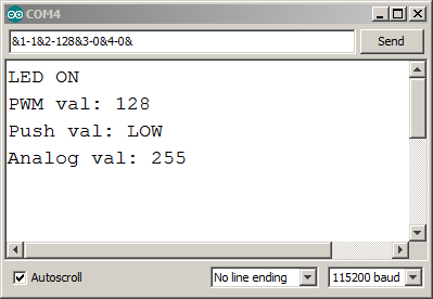
Test it opening the Serial Monitor and sending commands in the format: &c-v&
where c is the command number and v the value, for example to turn on the LED you need to send &1-1&, and to turn it off &1-0&.
For sending multiple values just concatenate the commands:
&1-1&2-128&3-0&4-0&
The last stream will turn on the LED, set the PWM to 128, read the status of the push button and the value of the ADC.
Notice how for commands 3 and 4, even when they do not need a value it’s clearer if you pass some number, like ‘0’, just to make all the commands look uniform, of course you can always send &3-&4-& but it looks ugly.
Explained
So how exactly the last program works?, is it magic?, maybe…
Remember we are sending a stream of characters with the next format:
&1-1&2-128&3-0&4-0&
Also be aware that communications sometimes fails and characters are lost (specially if you are using a Bluetooth dongle serial adapter), so in the end the Arduino could receive something like:
-1&2-128&3-0&4-0&3 or
1&2-128&30&4-0&&
Hopefully I designed it robust enough to keep it working even in such awful conditions.
readSerialBuffer()
So, we have the main loop function which only job is to be waiting for income data from the Serial port calling the readSerialBuffer() function. Look a this function closely, what is it doing?, it does two things:
- Read one single character from the serial buffer
- Take a decision based on the character:
- It’s a ‘&’?, then it means: 1. The next characters (up to a ‘-‘) represent the command portion of a command-value pair. 1. We are finishing a command-value pair, go to execute the last command stored in the ‘command buffer string’.
- It’s a ‘-‘?, then it means the next characters (up to a ‘&’) represent the value portion of a command-value pair.
- It’s a number (or at least not ‘&’ nor ‘-‘), store it in the current active buffer: “command buffer” or “value buffer”.
Note that I refer as buffer to the String variables, why? Because it sounds great!! Also because a buffer is like a stack of data, a place where you can store information for later consumption, I’m using Strings to accomplish this job because of the new utility inside the Arduino libraries for covnerting Strings to Integers, but you could perfectly adapt a simple char array or make a Linked List or parse the data as it comes.
executeCommand()
Now, this function will be executed each time a ‘&’ character is sent over serial. The command to be executed is the last command stored in the “command buffer string”, after that it will blank out the command and value buffers to be ready for the next command.
It uses the function .toInt() for converting the string representation of a command and a value to integers. So a command “1” will be 1, a value “128” will be 128.
Finally it calls executeCommandImpl(int command, int value) which actually executes the command: turn on/off the led, set pwm, retrieve analog value etc…
